A12 · Reference edition 2026.11
The 3-2-1 layout concept — Layout and sequence
Three, two and one contact groups describe a conceptual constraint arrangement for a suitable rigid part. Contact geometry still needs review.
Scope and purpose
Place the relevant elements in a visible order before completing the record. A diagram should distinguish position from sequence and should preserve the orientation used in the written notes. Review the example for a practical way to make the relationship explicit.
Working notes
This reference collection concerns light, offline dimensional-inspection layouts. It brings locating concepts, component descriptions and revision records together without substituting for an engineered fixture design. The drawings are original explanatory diagrams. Reference IDs identify documents, not commercially tested products. Read the scope and limitations alongside each example, and keep the actual part drawing and inspection requirements available when reviewing a proposed layout.
Practical example
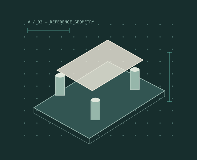
Sketch three primary supports before adding secondary and tertiary locators.
| Reference record | Interpretation |
|---|---|
| A12 | The 3-2-1 layout concept |
| Scope and purpose | Three, two and one contact groups describe a conceptual constraint arrangement for a suitable rigid part. Contact geometry still needs review. |
| Limits and interpretation | Thin walls and flexible parts need analysis beyond the rigid-body sketch. |
Review checklist
Identify the starting condition; mark the order or orientation; check that labels in the figure match the accompanying table.